|
© Copyright 2019
|
This section describes the basic function and the most important processes in the 2-stroke
cycle a tuner need to consider in general and with the Bimotion
2-Stroke tuning software in particular.
The high performance 2-stroke engine is a pulse resonance engine which means
that the operation in general and the scavenging in particular is
not only dependent upon the pulses created from piston pumping but
also from combustion properties. This is an important process to
understand and is the reason why not only the cylinder decides the
tuning degree but also the exhaust pipe, cylinder head and ignition.
The charging efficiency is dependent on the pulse energy created
from the cylinder pressure at exhaust port
opening.
Bimotion uses advanced analysis tools as 2-stroke simulation software and
finite element modelling for own research and to govern and
visualize the
theory.
|
|
A combustion engine is basically an air pump which follows the
thermodynamic laws, i.e, the relation between pressure, volume
and temperature. Air is pumped in, heated to expand and makes a
piston (or turbine) to move and create work. The work is
preliminary transported as torque and rotational speed, and
secondary as kinetic exhaust energy. The residual exhaust energy
can be used to run an additional turbine (turbo), expand in an
expansion chamber to pump air through the engine (2-strokes) or
just dissipate as sound (dragster's). In order to create as much
power as possible, the engine has to change the fuel from
chemical energy to as much mechanical work as possible. The
residuals are unburned fuel and heat loss. A great deal of the
piston work is lost by friction from all moving parts on its way
to the final destination, the ground. A 2-stroke bike with
efficient lubrication and without o-ring chain is usually
 loosing at least 15% of piston power. A 4-stroker looses a
lot more power with the additional moving parts as oil piston
ring, cams, valve train and balance axles.s.
loosing at least 15% of piston power. A 4-stroker looses a
lot more power with the additional moving parts as oil piston
ring, cams, valve train and balance axles.s.
When evaluation an engine from port timing you can measure the
piston displacement from Top Dead Centre (TDC) and calculate the
angles in the Bimotion programs, but you need to know rod length
to be exact. If this is not known, an approximate value of twice
the stroke can be used. You can also print this Degree Wheel and
paste on a CD to evaluate the port timing. (Click and print
picture in 12x12 cm).
The fuel property will decide the heat release, at which
rate the fuel will produce work. A well designed fuel is an
important factor to race engines. The heat release time from
combustion is mainly decided from the fuel properties, air/fuel
ratio and cylinder head design. The fuel ratio of H/C
(hydrogen/carbon) in the CnHm molecules varies, n and m takes
certain values for different fuels. During the combustion, the
molecules break down step by step with different heat release at
each step. 50% of the available heat is usually released within 5°
-10° ATDC (After Top Dead Center).
The picture shows the relationship to crank angle and crank moment. As a schedule example,
if fuel blend 1 releases most of the energy in a very short time after TDC, with
high peak pressure.
Blend 2 releases heat in a longer period of time with moderate
peak pressure, then the torque on the crank will be
different over the time for the two cases, thus also power.
|
|
Fuel blend 1
P1 = 10
MPa
L1= 5 mm (5-10 deg ATDC)
P2 = 1 MPa
L2 = 20 mm (60 deg ATDC)
M1 = 10*5 = 50
M2 = 1*20 = 20
Fuel blend 2
P1 = 8 MPa
L1 = 5 mm (5-10 deg ATDC)
P2
= 2 MPa
L2 = 20 mm (60
deg ATDC)
M1 = 8*5 = 40
M2 = 2*20 = 40
|
|
|
|
Now lets look at the total work:
 The resulting power output will be an integral of crank moment over time.
If the pressure on the piston varies as in the picture at a certain
rpm, the area below the curve could
represent the work. (A1 and A2). Note that A1 could be equal to A2 !
The resulting power output will be an integral of crank moment over time.
If the pressure on the piston varies as in the picture at a certain
rpm, the area below the curve could
represent the work. (A1 and A2). Note that A1 could be equal to A2 !
A high pressure peak for a short time might produce less work than a
low peak for a long time at a certain rpm. This means that a
low rpm engine will produce less power with the fast burning
fuel and visa versa. The engine stress and detonation risk
would also increase with the higher peak.
This is also why an engine with slow burning diesel produces more torque at low rpm than
with fast burning petrol.
|
|
|
The different heat release properties will suite different
engine characteristics and should be matched with the actual
exhaust port height which decides the opening pressure, i.e.
the charge pressure to the exhaust pipe.
 Fuel blend 1 will produce a lower pipe charge pressure than fuel blend 2 with the same exhaust
port. This could mean that the first choice is less sensitive
to exhaust pipe changes and more sensitive to cylinder head
geometry at a certain rpm.
Fuel blend 1 will produce a lower pipe charge pressure than fuel blend 2 with the same exhaust
port. This could mean that the first choice is less sensitive
to exhaust pipe changes and more sensitive to cylinder head
geometry at a certain rpm.
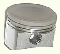
Another consequence to remember is that with a higher maximum
pressure, the piston will be more loaded, deformed and worn.
The picture shows a piston section cut from the exhaust side at maximum
combustion pressure. The stress pattern on the sides are recognized as common
worn areas.
|
|
|
2.1 Burn rate
During the pre-state of an combustion, the
flame front is expanding at approximately 20 -50
 m/s, i.e 70-180 km/h or 45-110 mi/h. Note that this velocity is varying with rpm and
mixture which means that we have to design the head to the worst case of our
application. This is also dependent on internal flow and heat.
m/s, i.e 70-180 km/h or 45-110 mi/h. Note that this velocity is varying with rpm and
mixture which means that we have to design the head to the worst case of our
application. This is also dependent on internal flow and heat.
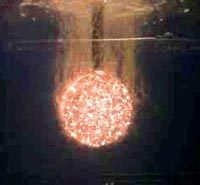
The picture shows three different ignitions at the same condition, a normal
operation at which the burn rate
varies.
We do not call this an explosion since it is a slow process. As a comparison, explosives as TNT
burns at a speed of 6000 m/s. When we get small local detonations which can be
defined as explosions, small pieces of the piston and head will be ripped off
and deform the metal. The piston may expand at the deck by plasticity and size
or blow a hole below the spark plug.
 The reason of detonations may be several, but there are dependency
 to squish band
design, temperature, rpm, mixture, compression, ignition setting, fuel atomization, exhaust pipe, etc.
The right picture is a plot of the gas velocity at the squish band and
piston velocity for a 125cc 2-stroke at 14000 rpm
as a function of crank degrees. Note that the piston is
moving at 20m/s away from the head already at 26 deg. ATDC. At this point, the
combustion pressure is still 70% of maximum on the piston. to squish band
design, temperature, rpm, mixture, compression, ignition setting, fuel atomization, exhaust pipe, etc.
The right picture is a plot of the gas velocity at the squish band and
piston velocity for a 125cc 2-stroke at 14000 rpm
as a function of crank degrees. Note that the piston is
moving at 20m/s away from the head already at 26 deg. ATDC. At this point, the
combustion pressure is still 70% of maximum on the piston.
The piston is not moving symmetrically during the stroke due to the
 crank and connecting rod geometry.
It moves faster at the top and slower at the bottom.
crank and connecting rod geometry.
It moves faster at the top and slower at the bottom.
By using a short rod, this will give a 2-stroke more time for scavenging which
is critical to high speed engines. The drawback is a high piston velocity at
combustion and decreased torque, but the benefits usually wins.
|
|
2.2 Thermal barriers, coatings.
The technique of thermal coating was developed in the space-, aircraft-, and power plant industry
at turbine blades as a shelter to heat shocks.
 The coating is a ceramic material which is extremely hard.
Piston engine combustion is not static, the magnitude and location
of the heat release is changing all the time. The process can be
resembled to a finger glove hitting the surfaces.
In that aspect, thermal coating to the piston crown with Keronite is popular, which is a plasma electrolytic oxidation (PEO) process. It mirrors the heat from the
metal and instead of heating it up, (that requires more cooling needs), the combustion energy is preserved and dissipated into piston work.
The process reduces the temperature of aluminum pistons by approximately 30*C (85*F).
Typically, there is a benefit on crown coatings when
 the piston has become too thin or too fragile for the application, e.g.
after tuning. The crown coating then becomes a kind of band-aid for a part
that might prematurely fail in an uncoated situation. Increased
power always increase the need of more cooling, not only from
combustion, but also from friction. Protection from heat and
friction is a necessity in modern race engines in order to
prevent metal melting and/or to minimize the wear.
the piston has become too thin or too fragile for the application, e.g.
after tuning. The crown coating then becomes a kind of band-aid for a part
that might prematurely fail in an uncoated situation. Increased
power always increase the need of more cooling, not only from
combustion, but also from friction. Protection from heat and
friction is a necessity in modern race engines in order to
prevent metal melting and/or to minimize the wear.
Composite Keronite-PTFE skirt coatings minimizes friction and allows pistons to run at
slightly tighter clearances than normal. This is especially
important on forged pistons that have a higher expansion rate
than cast pistons. There is no downside to a properly applied
piston skirt coating.
The inside of the cylinder ports are also treated to decrease heat
transfer between the metal and the in going air flow. Coatings
inside exhaust pipes are also common to prevent heat from
being transferred to the engine and cooling system by heat radiation and
convection.
|
|
 High efficient squish bands speeds up the combustion by adding more kinetic
(velocity dependent) energy to the gas mixture. They will also
transfer more heat into the head wall surface, which will be a
measured as a power loss through the cooling
system. Why?
High efficient squish bands speeds up the combustion by adding more kinetic
(velocity dependent) energy to the gas mixture. They will also
transfer more heat into the head wall surface, which will be a
measured as a power loss through the cooling
system. Why?
If you move your hand quickly in warm water or
blow on your skin in a hot sauna you will feel that the skin gets
warmer due to heat transfer from velocity. In the Bimotion Advanced Head program,
this factor is called the Area/Volume factor. If a geometry change
would give a higher factor with the same squish velocity, then we
could expect more heat loss due to the increased area. The actual
value don't need to be focused, but the changes to different head
shapes are interesting to observe, especially if cooling is a
critical factor in the original configuration.
With high performance engines kinetic energy is needed and with short
compression times (because of high rpm and short connecting rods) the
heat transfer will not necessarily be too high to the cooling
system. (Adiabatic compression). A head designed to a high tuning
degree will work best with a high speed engine, and a moderate tuned
engine will feel a great improvement with a moderate tuned head
instead of an head without a tuned squish band at all.
As you probably already noticed, the head geometry will be somewhat
dependent on the fuel type for a critical tuned GP engine and
require a lot of testing. As mention before, it's not easy to simulate a
head combustion by a software since it is irregular. But, there are
certain rules that can be used to predict the function by
software's. The Bimotion Advanced Head program uses a
lot of well calibrated methods from physical tests and experience to
design efficient 2-stroke heads.
The mechanism of a squish band is to push the gas as close to the
spark as possible at the ignition phase. During the squish, the gas
will also increase the vaporizing of the fuel and add kinetic energy
which increases burn efficiency. This is one of the reasons why the
ignition timing needs to be reduced with higher crank speed in a
2-stroke engine. The charging from the exhaust pipe is another.
Usually, squish velocities of 25-50 m/s are the upper limit dependent on
design, materials, cooling, fuel, etc. Too high squish velocity will
transfer too much heat from the gas to the surrounding metal and
will make the gas self detonate because of the energy increase.
|
 The fuel usually burn with this mentioned speed and it will serve as a good limit for the squish velocity.
A bad designed squish band will cause detonations which will destroy the
surrounding metal and sometimes hammer the piston, making it plastic
deformed over a big area and size due to the expansion.
When the gas at the squish band is moving into the centre, it will
have to increase its velocity due to the fact that the area is decreasing.
The red curve is shorter than the blue curve in the picture and with
a constant gap height the gas
must accelerate towards the red curve into the larger bowl volume.
The fuel usually burn with this mentioned speed and it will serve as a good limit for the squish velocity.
A bad designed squish band will cause detonations which will destroy the
surrounding metal and sometimes hammer the piston, making it plastic
deformed over a big area and size due to the expansion.
When the gas at the squish band is moving into the centre, it will
have to increase its velocity due to the fact that the area is decreasing.
The red curve is shorter than the blue curve in the picture and with
a constant gap height the gas
must accelerate towards the red curve into the larger bowl volume.
|
|
|
3.1 Head optimization
To optimize the squish behavior we need to have a constant squish velocity over the squish band. This is
 achieved by tapering the squish band height with the corresponding area ratio, so that
is the Squish Gap and
B
is the reduced height found as Y(C4) in the coordinate table of the program.
This height reduction also reduces the inefficient burned volume. The blue line shows the
mathematical correct squish band shape. We can see that a
strait line will approximate the shape perfect over the squish band width.
achieved by tapering the squish band height with the corresponding area ratio, so that
is the Squish Gap and
B
is the reduced height found as Y(C4) in the coordinate table of the program.
This height reduction also reduces the inefficient burned volume. The blue line shows the
mathematical correct squish band shape. We can see that a
strait line will approximate the shape perfect over the squish band width.
The squish taper angle is not constant, it increases with increased squish gap
A
. The taper angle is tangent with the piston edge at
B
.
The Head geometry gets more important with high squish velocities, the surrounding surface needs to
 be protected from the heat transfer. This can be achieved by different thermal barriers
(surface treatment) and with the gas itself. The secret key is
to avoid the hot gas to transfer heat. This is why we like
sharp inside corners from multistage heads. The two pictures
below shows the difference.
be protected from the heat transfer. This can be achieved by different thermal barriers
(surface treatment) and with the gas itself. The secret key is
to avoid the hot gas to transfer heat. This is why we like
sharp inside corners from multistage heads. The two pictures
below shows the difference.
In the right picture above
 there is no barrier to the head surface, more heat transfer to expect due to high gas velocity next to the head surface.
In the right picture beside, the small gas pocket above
the red line forms a natural barrier to heat transfer with low gas velocity next to the surface.
there is no barrier to the head surface, more heat transfer to expect due to high gas velocity next to the head surface.
In the right picture beside, the small gas pocket above
the red line forms a natural barrier to heat transfer with low gas velocity next to the surface.
|
|
 The same principal can be used to minimize heat transfer at the squish band. The
Yamaha TZ-head (right picture) uses both these ideas. The edges are marked.
The same principal can be used to minimize heat transfer at the squish band. The
Yamaha TZ-head (right picture) uses both these ideas. The edges are marked.
The final conclusion from this discussion is that the squish band at all times will
leak heat and transform useful piston work to kinetic gas
energy, a power loss source we need to get as much out of the
fuel as possible at combustion. If the squish band gets over
dimensioned then there will be more energy loss but no
improved combustion.
|
|
|
Many people talk about a port area as a target value and
indirect refers to a header area, with an area factor for the port.
That approach is a completely waist since port area don't give any
information about port shape. Time area is still the standard unit
for 2-stroke ports since at least 1971. An area change far up on the
port will give a completely different change than on the bottom of
the port. It would also affect the pipe differently. The time area
distribution is simply different over the port height because the
port is open different periods of time during the stroke.
In the Bimotion Advanced Port & Pipe
program we can see this distribution in a chart. (Se pictures below.) We should be more
careful with the machining precision at the upper part of the port
since that area is opened for a longer time.
|
|
|
A square port gives an increasing time area distribution with port height.
|
The distribution curve will also show the effect of
auxiliary exhaust ports which add blowdown time-area. We need a
certain blowdown time-area to equalize the cylinder pressure to the
crank case when the transfer ports opens. If this not works, we get
blow back to the crank case and that will drop the power
rapidly.
|
|
|
Auxiliary exhaust ports adds time area which can be seen in the
distribution chart.
|
|
|
|
The same port but without auxiliary ports.
|
Now, the blowdown timearea is not just a figure to
match, it is dependent on how strong pulses the pipe deliver. If the
pipes tuning degree is high (strong pulses), then we get away with
less blowdown time area !
And the transfer ports don't need so
much time for scavenging since the pipe suction wave is strong,
pulling out the gas from the crank case. We could then have wide and
low transfer ports. With low ports we can go for higher rpm without
getting blow back into the transfers.
Why do we need to take all
this in consideration for the exhaust port design? The answer is
that it is not only a time area target value, the whole system needs
to be investigated since there is an interaction, a balance between
pressures as the pipe is affecting even the reed valve and the
carburettor at BDC!!!
The normal procedure for race engine design
would be to keep the exhaust port as low and wide as possible and to
match the blowdown target (depending on pipe). The exhaust blowdown
target is a statistical value for the tuning degree decided by the
bmep target (braked mean efficient pressure). The port duration
should not exceed the recommended value.
|
|
When using the Bimotion Advanced Port&Pipe, you
should be aware of the validity of the calculations.
The time area values are only valid for the port apertures, not the
port channels. That is, it's a measure of what the port can
flow not what is really does flow. Bad shaped port channels may need
more port- and blowdown time-area than recommended, or more true,
the port channels may need to be reworked to a state of the art
shape with smooth surfaces. The recommendations for the higher
bmep's assumes this since it's based on race engines.
Now to a practically application, let us assume that you want more power
not only the first 10 minutes of a race but also all way into the
finish (less heat problems) and better drive, faster throttle response,
faster starts, less clutch slip and a higher appreciation of enjoy.
Perhaps you change parts as exhaust pipe, head, ignition, etc. and
convince yourself that it became an improvement. Or just different ?
Let us then tell you a "secret". There is a reason why the
fastest riders use special tuned engines, tuned with handcraft, not
bought as single parts from the shelf. An engine that is correct
adjusted or tuned manually is not believed to go faster. The
difference should be so obvious that you will be surprised and need
some time to adjust as a driver!
In order to make a qualified port work you either need long
experience and a flow bench and/or an efficient software to
calculate the correct relationships between port shapes and port
areas. Bigger holes doesn't necessarily flow more air during a whole
cycle since the flow is pressure dependent as well. There need to be
a balance between kinetic energy (air speed) and static pressure.
Big holes = high static pressure and low kinetic energy, and visa
versa. The flow must be maintained until the ports are closed,
otherwise backflow will occur with power loss, especially below peak
power. But high speed power=big holes (?)... Yes, but this is why it
is very important to locate the port area exact where it is needed,
at the correct time of the cycle where it will meet the pressure
pulses from the exhaust pipe most efficiently.
By other words, we need to work very carefully with port shapes and
port timing. Not port area only. The Bimotion Advanced Port & Pipe
program has been specially designed to take most of these parameters
into account. It's not
possible to tune a single port without having the whole picture.
How strong pulses can the pipe cope with ?
How much responsibility is laid on the pipe dependent on the exhaust
port shape ?
Does the transfer ports match the pipe pulses ?
Does the transfer flow match the intake capability ?
etc, etc.
By using time-area (flow capability) as a design target for a
certain tuning degree and a lot of recommended combinations we can
by 40 years of experience say what will be a successful combination
and what will not. In fact, simulated and tested designs usually
shows that it is not worth the extra work to try and find a more
efficient combination or shape unless there is a large budget for
test, simulation and manufacturing.
But even if there is, this simplified method is needed in order to
get a correct basic configuration as
a starting point to more advanced analysis.
 When 2-stroke cylinders are manufactured, different manufacturing- and production limitations needs to be accounted for.
It could be cast draft angles, tooling split lines, tooling wear, production
economy, etc. By other words, it's not possible to cast all shapes and
desired surfaces from manufacturing. These built in restrictions
must be adjusted by hand if maximum performance is wanted.
Apart from the surface finish, the port shape can also be
adjusted to fit the system. Any adjustment done should be possible
to motivate by the tuner, otherwise it shouldn't be done. The
picture shows the difference between raw manufactured surfaces and
adjusted shape and area. The increased exhaust flange area and port
time-area must be correct matched to the exhaust pipe, .i.e. the
standard pipe may need to be changed to fit the new port properties.
When 2-stroke cylinders are manufactured, different manufacturing- and production limitations needs to be accounted for.
It could be cast draft angles, tooling split lines, tooling wear, production
economy, etc. By other words, it's not possible to cast all shapes and
desired surfaces from manufacturing. These built in restrictions
must be adjusted by hand if maximum performance is wanted.
Apart from the surface finish, the port shape can also be
adjusted to fit the system. Any adjustment done should be possible
to motivate by the tuner, otherwise it shouldn't be done. The
picture shows the difference between raw manufactured surfaces and
adjusted shape and area. The increased exhaust flange area and port
time-area must be correct matched to the exhaust pipe, .i.e. the
standard pipe may need to be changed to fit the new port properties.
|
|
When the exhaust port shape is
decided from time area targets etc. we can dimension the exhaust
pipe header diameter. This is critical to the pipes blowdown
efficiency and the pressure build up. We need to pressurize the pipe
with a strong and not too short pulse and the length will interact
with the pulse resistance to create the necessary pulse shape. This
means that it is not always better to use a diverging header (L1),
sometimes a diverging header may result in that the cylinder exhaust
evacuation is too rapid and causes the pipe to 'loose the breath'
during the stroke. It will gain power at high rpm but lose in the
lower range, mostly okay for race engines though. The phenomena
needs to be viewed in a simulator to be fully understood.

To simplify some we say that the
first diffusor (L2) acts in the lower rpm range and the last
diffusor (L4) in the upper range. The rear baffle (L6,L7) angle
decides the top end rpm range and power 'hit'. Steeper angles will
increase the pulse strength and decrease the pulse length, i.e.
shorten the rpm range at which the usable power is produced. The
internal length between the diffusors will also decide the power
production characteristics, so if the first diffusor is relative
long then it will gain power in the lower rpm range etc. A pipe that
is pressurized with an early opened port (long duration) will be
able to retain the pressure through the steep angles and deliver a
strong suction pulse back at BDC. With strong pulses engaged we
don't need too large/high transfer ports. The pipe will then help
and pull out the gas from the crankcase, even manage to open the
reed valve and pull more air through the engine. When the transfer
ports are closed, a second returning wave in the pipe pushes back
the fresh gas that was spilled out into the header, in the remaining
blowdown window that is. The charging pressure is often in the
region of two atmospheres (bar) and way over that.
This is why the pressurization of
the pipe needs to be well investigated together with the exhaust
port, we simply cannot fit any pipe to an engine. It have to fit the
exhaust port and even the transfer ports too!!
Finally, the stinger need to be large enough to let the engine breathe. A small stinger diameter
(and long stingers) will increase the internal pressure and power
but also make the engine run hotter. The length becomes
critical to pulse resonance over about 9000 rpm. At that point the
plunging effect at the stinger end will interact with the pipes
internal pressure and help to lower the evacuating pressure at
piston BDC. However, for high rpm engines, the stinger in general
needs to be smaller than on low rpm engines. High frequency pulses
have shorter wave length and will fit a smaller pipe better. But
since the high rpm engine also needs to breathe more this can often
even out.
|
7. Case Study
 Download the Bimotion case study of Kawasaki's
legendary KX500 2004 motocross engine !
Download the Bimotion case study of Kawasaki's
legendary KX500 2004 motocross engine !
A step by step guide about how to calculate a 2-stroke.
Click the picture !
|
|
|

